GynaeCam: Control & Lighting Electronics
Overview
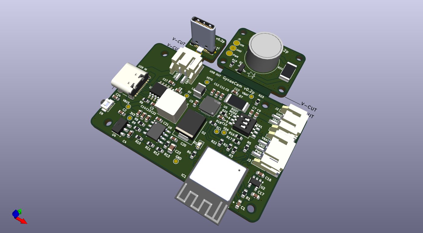
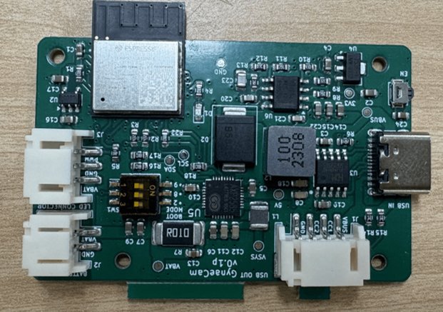
I led the electronics design for GynaeCam, a portable, battery-powered camera device developed at IIT Bombay. The system has two boards. The control board handles USB-C power input and negotiation, battery charging and monitoring, and the device’s microcontroller. The lighting board carries a high-power LED that illuminates the camera’s field of view. Both boards were taken from schematic to assembled prototype over two revisions (v0.1p and v0.2p).
Salient Features
- ESP32-C3 Microcontroller:
- An ESP32-C3-MINI-1 module with Wi-Fi and BLE, programmed over UART, with a DIP switch to select the boot mode.
- USB-C Power Delivery:
- A CH224K controller negotiates the supply voltage over USB-C PD, and dedicated USB-C in and out ports route power and data.
- Battery Management:
- An AXP2585 handles Li-ion charging and fuel gauging, and reports battery state to the MCU over I²C with an interrupt line.
- LED Driver:
- A TPS54560 switching regulator drives a Cree XLamp XP-L high-power LED. The MCU controls brightness through PWM dimming.
- Thermal Design:
- The LED sits on its own lighting board, with thermal vias under the LED pad to carry heat away.
- Manufacturing-Ready Layout:
- A 4-layer PCB, panelized with V-scored breakout boards (the LED board and a USB-C plug board).
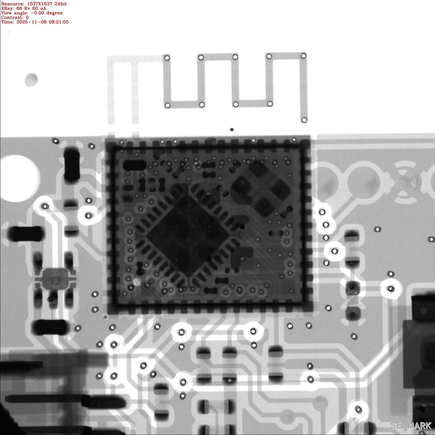
- Each revision is exported with gerbers, BOM, pick-and-place files and an interactive assembly guide, assembled at JLCPCB, and inspected by X-ray.